Friday 30 June 2023

Types of Relays Used in Air Circuit Breaker (ACB)


Types of Relays Used in Air Circuit Breaker (ACB)

Basically internal protection and tripping applications, relays are used internally in air circuit breakers to make it more efficient in operation. And generally three types of relays are used in air circuit breaker.
  • shunt coil relay
  • Under Voltage (UV) Relay
  • closing relay

Shunt Coil Relay

Basically this relay can also be called as power relay for air circuit breaker. Shunt coil relay is an automatically controlled relay, which can be operated remotely to open or close a circuit breaker.
Just like a PLC operates a relay, this shunt coil relay can also be operated (on or off) by it. The operation of this relay directly opens or closes the circuit breaker.

Under Voltage (UV) Relay

Basically this relay is used to detect under voltage in the incoming power supply. Overvoltage is a simple natural problem that the circuit breaker will detect and trip the path. When the incoming voltage is low and usually less than 380 V, the load connected in the circuit breaker will work in low efficiency and also get damaged after a long time. So, an under-voltage relay is used to detect under-voltage problems and trip the circuit for it immediately. You can set an under-voltage threshold in the circuit breaker, which will then automatically perform this protection function.

Closing Relay

Basically it is same as shunt coil relay. It can also be controlled remotely via PLC, and it will automatically open or close the circuit breaker

Friday 1 July 2022

MCCB TERM

 Iu

 Rated uninterrupted current (Iu) The rated uninterrupted current of an equipment is a value of current, stated by the manufacturer, which the equipment can carry in uninterrupted duty.

KA rating

kA rating of an MCB or an MCCB is the maximum current it can safely interrupt in case of a short circuit. If the current goes beyond this value, the circuit breaker could be damaged. kA rating is known as the short circuit withstand capacity or ultimate breaking capacity of a circuit breaker

Icu

unlimited break Capacity of the circuit breaker Which means the circuit breaker can break the maximum fault current without damage. Typically for MCB the maximum Icu will be 6KA to 10 KA for MCCB Icu may be 200kAmps.

Ice

Ics is the amount of current that the circuit breaker can safely withstand without being damaged for example 6 kA or 6000 A and remain usable. Icn is the amount of current the circuit-breaker can safely handle but would not remain usable.

Ue

Rated working voltage (Ue) is the continuous operation voltage for which the MCCB is designed. This value is typically equivalent or close to a standard system voltage. Operating short-circuit breaking capacity (Ics) is the highest fault current that the MCCB can trip without being damaged permanently.

Ui

Rated insulation voltage (Ui)

This is the value of voltage to which the dielectric tests voltage (generally greater than 2 Ui) and creepage distances are referred to. The maximum value of rated operational voltage must never exceed that of the rated insulation voltage,

Uimp

Rated impulse-withstand voltage (Uimp)

This characteristic expresses, in kV peak (of a prescribed form and polarity) the value of voltage which the equipment is capable of withstanding without failure, under test conditions. Generally, for industrial circuit-breakers, Uimp = 8 kV and for domestic types, Uimp = 6 kV.


MCB data


  • Product Modal No
  • Max Current Rating
    (6, 10, 16, 20, 25, 32, 40, 60, 63 etc)
  • Operation Symbol
  • Breaking Capacity Type
  • Breaking Capacity (Max Short Circuit Current)
  • Operating Voltage(230V, 400V, 440V)
  • Tripping Curve Type
  • Energy Class
  • ON-OFF Indication
  • Catalog No
  • Product Modal No
  • All reputed manufacturer has a particular code of each device type. It will be very easy to communicate with seller or manufacturer, if you quote the model no., in case of any service complaint.
  • Max Current Rating
    (6, 10, 16, 20, 25, 32, 40, 60, 63 etc)
  • As shown in example, it is mentioned C20 (and in the below image, it is B25). First letter is showing the characteristics curve. There are three characteristics curves (In common use) available- B C & D. B curve indicates that short circuit rating of device is in range of 3-5 times of standard rated current (Which means, TIME for Trip initiation i.e. the less rating of the the time will be Fast acting, like for protecting sensitive Electronics devices and equipment). C curve indicates it to be 5-10 times and D curve indicates it to be 10-20 times. Be very careful while selecting this. On a resistive load (say heater, normal lighting load) it will B Curve, for inductive load (Like pump, Motors etc.) it will be C curve and for highly inductive or capacitive load it will be D curve. The numeral part indicates rating of MCB in Ampere. In the given example it is 20A. MCB rating is very important and be very precise about it.
  • Operation Symbol
  • It is in Volts and is the operational voltage for which current rating is said. In three phase it is usually 400V or 415 V. For single phase it is 230V or 240V. Choose as per your application only.
  • Breaking Capacity Type

  • Breaking Capacity (Max Short Circuit Current)
  • Breaking capacity can be defined as the maximum level of fault current which can be safely cleared. It is written as in numerals like in in example it is 10000. It means it 10000A = 10kA. Choose breaking capacity as per your fault level possible. Since it is the parameter which may increase or decrease the cost, so it should be properly decided. Breaking capacity should be higher than the possible fault level. For domestic application where fault level cannot be calculated easily, it advisable that go for a standard breaking capacity of 10kA which is easily available. Please note that this rating is mentioned as per testing made on basis of IS 60898. If it is for IEC60947-2 then it need to be mentioned separately.
  •  Voltage(230V, 400V, 440V)
  •  It is in Volts and is the operational voltage for which current rating is said. In three phase it is usually 400V or 415 V. For single phase it is 230V or 240V. Choose as per your application only.
  • Tripping Curve Type
  • Energy Class
  • MCB normally work on current limiting feature. It means that it does not allow fault to get it’s peak and trip before that. But since there is some time consumed in tripping, fault current will create some energy which will exist in system. This energy is termed as let through energy. For efficient MCB operation it should be limited. On basis of amount of energy it is classified in class 1, class 2 and class 3. Here Class 3 is best which allows maximum 1.5L joule/second. This is being tested as per IS 60898.
  • ON-OFF Indication
  • It shows the ON-Off Indication while in operation. Never buy an MCB which don’t have clear status indicator because serious damage may be occurred with ON-OFF confusion of the device.
  • Catalog No
  • Most of the MCB manufactures put the catalog number of the MCB products. This code provide the overall information on the manufacture website such as MCB specification and Datasheet ect.

Saturday 8 October 2016

Category for Chargeman


No
category
certificate
classification
Low Voltage System (Below 1000V)
1
AO
PJ1
Low Voltage System (Without Aerial Line and Power Station)
2
A1
PJ2
Low Voltage System (Without Power Station)
3
A4-2
PJ32
Low Voltage System (Without Aerial Line and Synchronizing of Generators)
4
A4-1
PJ3
Low Voltage System (Without Synchronizing of Generators)
5
A4
PJ4
Low Voltage System
High Voltage System ( 11kV or 33kV)
6
BO-2
PJ52
High Voltage System (Without High Voltage Aerial Line and High Voltage Power Station; and Without Low Voltage Aerial Line and Low Voltage Synchronizing of Generators)
7
BO-1
PJ5
High Voltage System (Without High Voltage Aerial Line and High Voltage Power Station; and Without Low Voltage Synchronizing of Generators)
8
BO
PJ6
High Voltage System (Without High Voltage Aerial Line and High Voltage Power Station)
9
B1
PJ7
High Voltage System (Without High Voltage Power Station)
10
B4
PJ8
High Voltage System

Wednesday 31 August 2016

GOODS HOIST

Kali ini nak bercerita sedikit berkenaan goods hoist atau lift barangan. Satu keperluan penting bila melibatkan pemindahan barang dari satu tingkat ke satu tingkat.

Oklah... cerita ringkas.. straight to the point. Dalam sistem hoist ni mesti ada panel kawalan (seperti dibawah).


Ada motor dan kabel, seperti gambar kat bawah.


dan dah tentunya ada cage atau sangkar. Atau ada juga panggil "car". Itu saya tak nak cerita, kalau sempat saya tambah. Kali ini nak cerita pasal panel dan motor je. Biasanya mende ni yang ada problem yang susah sikit nak tackle.

PANEL KAWALAN


Dalam gambar diatas ditunjukkan kedudukan setiap komponen dalam panel tersebut. Voltage kawalan yang digunakan adalah 24VDC. Ini dibekalkan oleh contoller adaptor atau power supply seperti dalam gambar. Pandangan dekatnya adalah seperti dibawah.


Power supply ini dilengkapi fius dan MCB untuk keselamatan.


Pandangan dekat di bahagian terminal.


Seterusnya ia disambungkan kepada suis, relay dan alat kawalan lain.


Litar kawalan ini seterusnya disambungkan kepada penyambung yang diletakkan dibahagian bawah panel.

Tandaan litar kawalan yang berkait dengan penyambung ada diletakkan pada pintu panel.


PERJALANAN MOTOR

Power supply dan kawalan kemotor dikawal oleh satu MCB 3P dan satu set interlock contactor (foward reverse). 


Pada motor tersebut juga ada terpasang satu sistem brek yang hanya akan dilepaskan apabila bekalan diberikan kepada motor. Kawalan brek tersebut dibuat dengan menggunakan solenoid yang akan menarik mekanisma untuk membuka brek ketika bekalan diberikan dan melepaskannya ketika tiada bekalan. Dengan cara ini, hoist akan terhenti ketika tiada bekalan diberikan.


atau dengan kata lain, ketika bekalan diberikan kepada motor untuk menghidupkannya, pada masa sama, bekalan diberikan untuk melepaskan brek. Kedudukan brek adalah bersebelahan motor.


Gambar soleniod dan brek secara dekat


Ketika bekalan dihidupkan, solenoid akan di menarik pelepas brek kearah bawah, seperti anak panah arah anak panah dibawah.


Dibawah ini adalah gambar solenid yang perlu ditukar sekiranya berlaku kerosakan brek. Biasanya solenoid in perlu ditukar apabila melebihi 1 tahun (bergantung kepada kegunaan). Untuk melepaskan brek secara manual, pelepas brek boleh ditekan kebawah seperti arah anak panah.


Peringatan, JANGAN USIK SOLENIOD SEBELUM PENGGANTUNG HOIST DIPASANG. Ini penting kerana, sebaik sahaja solenid diusik, kemungkinan hoist akan turun kebawah adalah besar. Pelepas brek tersebut boleh dilepaskan secara manual dengan menekan menggunakan tangan seperti arah yang sama seperti penarikan oleh solenoid (seperti gambar yang mempinyai anak panah diatas diatas).


Nota :

Antara tanda-tanda brek ada masalah adalah :-

- Ketika turun kebawah, hoist akan turun dan terus turun walam pun sudah mencapai tahap terendah yang disetkan.

- Ketika ada beban, lift akan turun ketika berhenti di tempat tinggi. (motor tidak dapat berhenti bila ada beban).

- Bunyi motor bising seperti berat atau motor berjalan ada bunyi geseran tinggi.

- Berbau hangit.

- MCB motor trip dan motor tak dapat dihidupkan buat sementara waktu. Pemeriksaan terhadap bekalan kuasa pula didapati dalam keadaan normal/biasa.


Saturday 27 August 2016

MUAR BLACK OUT 14/0/2016 TO 16/08/2016

Gambar dibawah adalah gambar-gambar bekalan sokongan dari TNB ketika Black out disebahagian besar Bandar Muar. 

Ianya bermula pada 14/08/2016 sekitar jam 6.00pm sehingga jam 09.00 pm. Disebabkan kerosakan awal tidak dapat dikenal pasti, esoknya iaitu pada 15/08/2016, kerosakan berulang. Pada jam (sekitar) 6.00pm, Bekalan sokongan dihantar oleh TNB. Dikatakan sebanyak 14 generator mudah alih disediakan di kawasan terbabit sekita Muar. Meliputi Jalan Salleh, Jalan Abdullah dan lain-lain kawasan.


(didalam gambar ini saya cuba padamkan identiti orang dan kenderaan sedapat mungkin)

Kerosakan dikatakan berpunca dari kerosakan bawah tanah kabel 11KV di kawasan menghala ke Bukit Pasir.

Bekalan pulih sepenuhnya sekitar jam 4.30pm jam , pada 16/08/2016.


Bila berlaku black out sebegini, apa yang terlintas di fikiran saya apabila diberitahu bekalan sokongan dihantar... adakah generator sokongan tersebut dapat menampung kegunaan yang ada? Ini juga adalah peluang untuk memberi tunjuk ajar kepada mereka yang baru.

Kebimbangan ini timbul kerana premis dibawah jagaan saya mengunakan arus sekitar (maksima) 600A. Oleh itu saya kena pastikan kemampuan bekalan sekurang-kurang setara dengan permintaan keseluruhan terhadap alat ubah sedia ada.

Alhamdulillah... generator sokongan (dalam gambar) mampu menjana sehingga 1250KVA.

Bila di sebut nilai ini, apa nilai KW atau Amp yang boleh ditampung.

Disini sekadar kiraan ringkas untuk panduan (sendiri...)

1250KVA ---> 1250 x 0.8

= 1000KWH (biasanya p.f genset adalah 0.8)

arus yang boleh dibekalkan 

= 1.7*1000

= 1700 A (perfasa)

kegunaan dibenarkan adalah 80% dari nilai tersebut.

oleh itu arus maksimum adalah

= 1700 * 0.8

= 1360 A.

Didapati bekalan oleh genset ini lebih besar dari yang boleh dibekalkan oleh alat ubah sedia ada iaitu ada iaitu 1000A.

Oleh itu tiada masalah dalam bekalan terhadap premis sedia ada.

Nak senang kiraan... ambil je... berapa nilai KVA yang boleh dijana, itulah nilai arus yang boleh dihasilkan. Mudah dan selamat, walaupun kurang betul. 

(Maksud saya : secara ringkas 1250KVA boleh tampung 1250A perfasa... tak yah pening... dah tentu selamat)

Nota : Ini adalah kiraan secara ringkas untuk memudahkan anggaran. Jika ada yang perlu di perbetulkan, di persilakan.


LITAR KAWALAN MOTOR

litar ni member minta buatkan... untuk mudahkan rujukan, saya masukkan kat sini untuk dikongsikan.

Litar kawalan simple untuk kawalan motor/water pump. Kenapa dikatakan simple..., cuma pakai timer relay dan timer sahaja dah boleh pakai. OK lah... litarnya seperti dibawah.


untuk lebih jelas, litar di atas di ubah posisi...


Jika ingin mengunakan DOL yang tersedia dengan kotaknya (seperti gambar) , sedikit ubahsuaian perlu dilakukan pada starter DOL tersebut. Pada DOL biasa, contactor dihidupkan oleh suis tekan (bewarna hijau) dan dimatikan oleh suis bewarna merah. Dengan ubahsuai litar ini, contactor akan dihidupkan atau dimatikan dengan kawalan sepenuhnya oleh litar diatas. Masa hidup atau mati pam ditentukan oleh masa yang di set (tala) pada pemasa (timer relay) yang ditandakan.  Timer T1, T3, T5 adalah masa yang disetkan untuk pam hidup (ON), sementara T2,T4, T6 pula masa disetkan untuk pam mati (OFF). 

Pada litar tersebut, thermal overload dikekalkan dan berfungsi untuk mematikan litar andainya ada kerosakan pada sambungan litar : 

Sambungan litar pada DOL

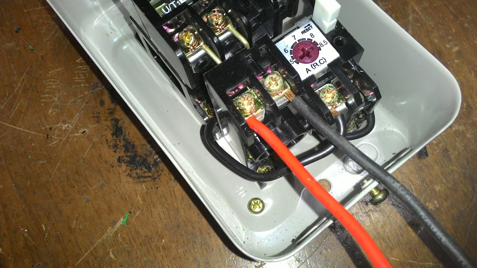
Sambungkan L,N (kabel merah dan hitam)  kepada punca kuasa (power supply)

Sambungkan kabel kuning kepada kabel yang ditandakan "pump contactor"


Dibahagian LOAD pula, sambungkan  kepada motor. Pastikan sambungan pada bahagian thermal overload tidak dicabutkan dan dalam keadaan baik. Sekiranya controller  ini "trip" disebabkan overload, butang reset sedia ada boleh digunakan seperti biasa.


Gambar : Litar penuh


Sekiranya DOL yang dibuat sendiri, pastikan thermal overload dipasang pada litar untuk keselamatan. 


Sekiranya corak atau pola ini mahu dipanjangkan lagi, Litar diatas boleh ditambah dengan pola yang sama. Maka corak ON/OFF boleh ditambah bergantung kepada bilangan relay dan timer digunakan. Setiap ON/OFF tambahan memerlukan tambahan dua (2) timer dan satu(1) relay. Sambungan pada litar ditandakan dibawah boleh di buang atau ditambah untuk memanjang atau memendekkan corak yang dikehendakki.


SEKADAR RUJUKAN

Dibawah ini adalah gambar starter DOL yang digunakan.


Gambar DOL asal


Gambar DOL yang di ubah pendawaiannya


Gambar : sambungan di bahagian bekalan dan kawalan


Gambar : Sambungan dibahagian beban atau sambungan ke motor


Perhatikan sambungan pada bahagian Thermal Overload. Ianya tidak boleh dibuang untuk mememastikan peralatan atau litar ini mempunyai ciri-ciri keselamatan.


Gambar : Pandangan sambungan dari tepi 


contoh contactor / thermal overload yang boleh digunakan


NOTA :

A1, A2 : CONTACTOR COIL

13, 14 : NO (normally open connection) - biasanya untuk litar kawalan

21, 22 : NC (normally close connection) - biasanya untuk litar kawalan

1L1, 3L2, 5L3 : POWER SUPPLY - litar kuasa

2T1, 4T2, 5T3 : LOAD - litar kuasa


95, 96 : (normally close connection) - Untuk litar kawalan. Sambungan disini perlu untuk sambungan kepada thermal overload.

97, 98 : (normally open connection) - Untuk litar kawalan. Sambungan ini biasanya digunakan untuk menunjukkan overloada trip.


Semoga ianya berjaya digunakan.


Wassalam.